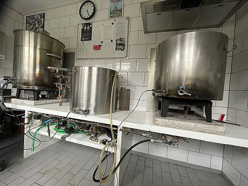
My Brewing Setup
This page gives a detailed description of the various components of my brewing setup. For a few specific components, such as for the electronics and the software, separate pages have been made. The brewing setup consists of the following main components:
- The Hot Liquid Tun (HLT): the kettle on the left
- The Mash/Lauter Tun (MLT): the kettle in the middle
- The Boil kettle: the kettle on the right
- The magnetic pump: the heart of the brewing setup
- The Solenoid Ball Valves: the fluid-switches of the brewing setup
- The Counter flow chiller (CFC): the cooling unit that cools down the boiling hot wort down to room temperature
- The Gas Burners: two burners of 24 kW (!) each, adjustable between 0 % and 100 % power (modulating)
- The Climate Chamber: optimal fermentation temperatures, summer and winter
The Hot Liquid Tun (HLT)
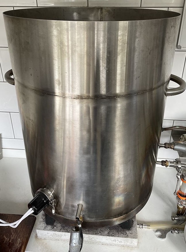
The HLT, or the Hot Liquid Tun, is the pan at the left side of the brewing system. It can contain up to 200 litres. The HLT contains a counterflow heat exchanger controlled by a second pump. The mash water flows through the heat exchanger and is heated to the same temperature as that of the water inside the HLT. The counterflow heat exchanger is a bit unusual and not often seen inside a HLT. But heat-transfer from HLT to MLT is much better than only with a heat-exchanger. Key point is that water should be moving inside the HLT for efficient heat transfer. And the counterflow heat exchanger with the pump is very efficient at doing so. In the picture, several connections can be seen:
- The connection at the front is connected to solenoid ball valve V2 (see How does it work?). You can also see a manual ball valve (with the blue handle), but this one is no longer in use.
- Just above this connection, there's a connection for the digital temperature sensors (I2C: LM92 and One-Wire: DS18B20), needed for the brew program. The pipe goes into the HLT, which assures a good temperature reading.
- At the left, a two-inch tri-clamp flange is welded for an electric heating-element. Currently a 3 phase heating element of 3 x 1500 W is mounted. The brew program actively controls two phases (1 x 1500 W and 1 x 3000 W). With this setup it is easy to replace the existing heating-element for a more powerful one.
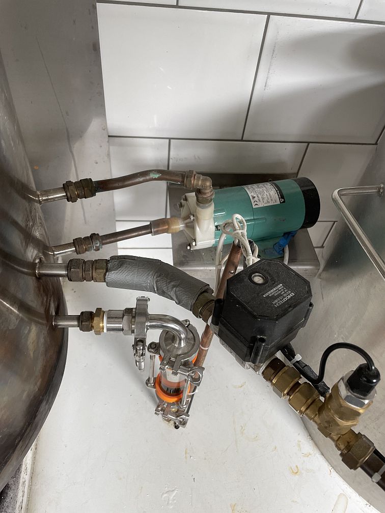
- At the right side of the pan there are four connections (all welded) for the heat exchanger inside the HLT. The connections on the left are connected to ball valve V4 (also shown on the picture). The upper-left connection is connected with a copper pipe to the return manifold in the top of the Mash/Lauter Tun (MLT). The connections on the right are connected to a second pump that is used to pump the water in the HLT through the heat-exchanger.
Heating the water is done electrically and with a gas burner (24 kW, 81000 BTU/hour). The HLT is located on top of a stand. The gasburner (the grey metal box) is mounted to this stand. The stand itself stands on top of a concrete foundation, which absorbs some of the heat the gasburner produces. The picture also shows the gas connection (22 mm), which goes through the concrete foundation to the gasvalve (mounted underneath). The gas valve is controlled by the brewing program. To facilitate a good heat exchange from the HLT to the MLT, a counterflow heat-exchanger is mounted inside the HLT. Water from the HLT itself is sucked into this heat-exchanger by an outside pump. This setup forms an efficient way to transfer heat from the HLT to the MLT.
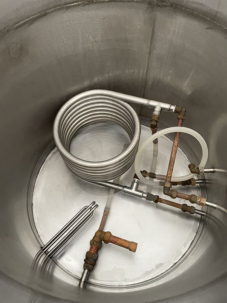
This picture shows the interior of the 200 L HLT. The following items are shown:
- An outlet pipe in the middle with a silicon hose attached to it. This enables the pump to suck out almost all the water from the pan. This pipe is connected to ball valve V2.
- The counterflow heat exchanger which consists of 4 pipes.
- A copper pipe which points sideways. This pipe contains the digital temperature sensor.
- The 3 phase electric heating-element.
 Back to the Top of the Page
The Mash/Lauter Tun (MLT)
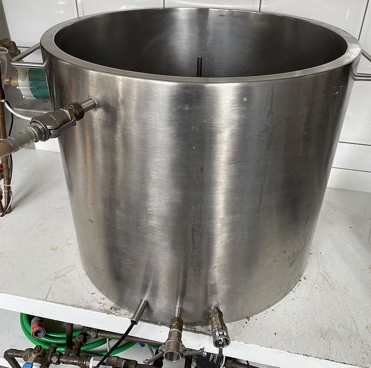
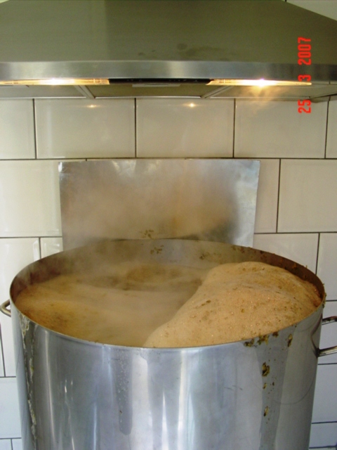
The Mash/Lauter Tun, or MLT for short, is the kettle in the middle of my setup and can contain up to 115 litres. This kettle is the heart of my brewing setup. It is a double-walled kettle, which is built by a professional metalworker. The inside diameter is 54 cm, the wall thickness is 2½ cm and the height is 50 cm. The space between the walls has been filled with glass fibre. The kettle isolates very well, even at 80 °C on the inside, you can't feel anything on the outside! External to the MLT, the following connections are shown:
- A connection for the digital temperature sensor, shown on the bottom left. On the picture, you can see the cable entering the kettle.
- The connection in the middle is a camlock coupling, where a silicone hose can be attached to. This silicone hose connects to valve V1 (see How Does it Work? for more details) and is connected to a filter at the bottom of the MLT.
- The connections on the right are the connections for a sight-glass, so you can manually view the MLT volume.
- The isolated connection in the top is connected to the heat exchanger in the HLT. This connection leads to the return manifold in the top of the MLT.
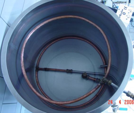
This picture shows the interior of the MLT. It contains the following items:
- The return manifold in the top. This is a circular ring with holes on the inside, see picture below.
- The manifold at the bottom of the kettle. This is a ring with grooves and holes at the bottom. The wort is sucked from the kettle through this, while leaving the malt in the MLT.
- The water tight pipe which houses the digital temperature sensor.
- The pipe leading to the sight-glass. This is an open connection. Before you pump water in the MLT, the sight-glass should have been mounted!
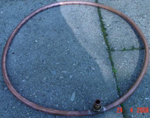
This is a detailed picture of the return manifold in the top of the MLT. You can see the holes on the inner side of the ring. These holes make sure that the wort lands gently on top of the grain bed. By making sufficient holes, there's almost no foaming.
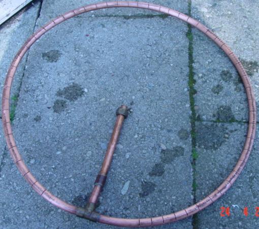
This picture shows the bottom view of the manifold at the bottom of the MLT. This is the side that is actually on the bottom of the MLT! Many grooves have been made, through which the mash water can be sucked from the kettle. The grain remains in the kettle and will function as a filter bed. The MLT filter is connected with a quick-connect coupling to the connection in the middle of the pan. The MLT filter is placed at the bottom of the MLT. In this way it is connected to ball valve V1, which controls the mash water flow. Many home-brewers use either this or a false bottom. Such a filter looked very practical to me and it works excellent (again this is not something I invented but was seen on sites from various home-brewers).
Back to the Top of the PageThe Boil kettle
The boil kettle is the right most kettle of my brewing setup and is made completely of stainless steel. Again, it is made by a professional metal worker. The inside diameter is 60 cm, the height is 50 cm, resulting in a net volume of 141 litres. But if you want a decent boil, it is better to limit the amount to 100 litres.
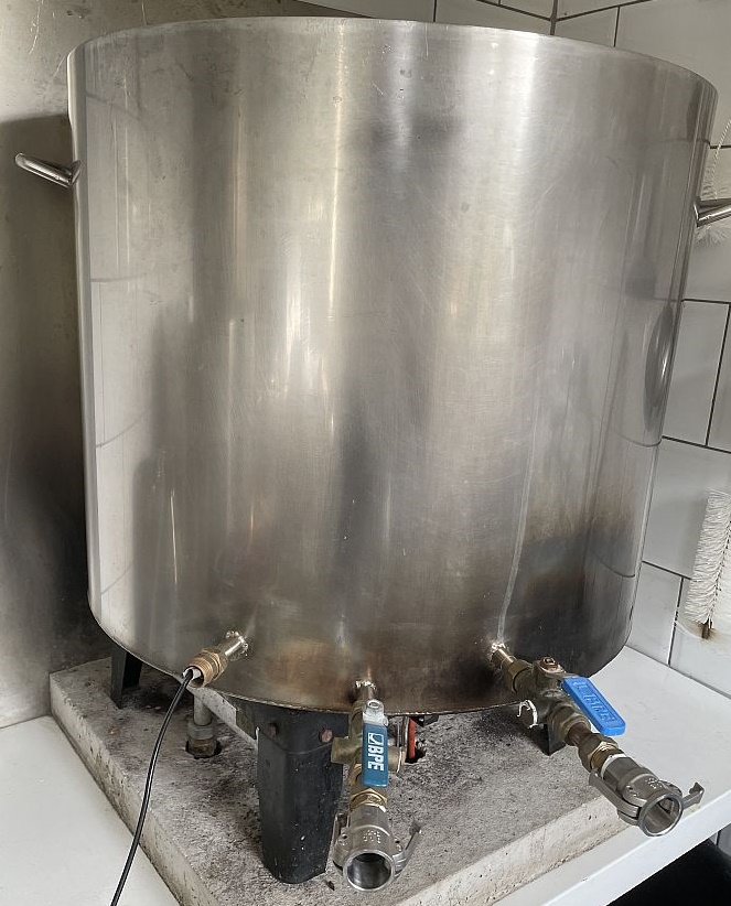
The boil kettle has three connections, The connection on the left leads to a closed pipe inside the boil-kettle. This connection is meant for a digital temperature sensor. The connection in the middle is connected to ball valve V3 (which is connected to the pump inlet with a silicon hose in the camlock coupling) and is used to transfer wort FROM the boil-kettle. The pipe on the right is connected to ball valve V7 (which is connected to the pump outlet) and is used to transfer wort INTO the boil-kettle. See How does it work? for a detailed description of these valves. The boil-kettle stands on a gasburner. The gas-valve for this burner is controlled by the brewing-electronics.
The boil kettle has manual valves attached to the input and output pipes. This is convenient for cleaning when the camlock hoses are removed.
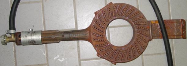
The copper manifold at the bottom of the boil kettle is nothing more than a copper circle that is connected with a quick-connect coupling to the pipe in the middle of the boil kettle. The manifold has many cuts on the bottom side (the side that is placed at the bottom of the boil kettle). After boiling is done, valve V3 is opened and wort is transferred to the counter flow chiller, which cools the wort. The hop flowers can not pass the cuts in the manifold and remain in the boil kettle. Hop pellets can be used too, but you have to add a five minute rest before the pump is switched on. Otherwise, the manifold can become clogged.
Back to the Top of the PageThe magnetic pump
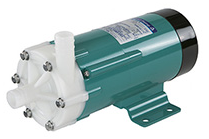
The pump forms the heart of my brewing setup. It is a so-called magnetic pump drive. This means that the motor drives a magnet that rotates. Due to the magnetic force the pump internals are turning. There is no mechanical connection between the motor and the pump, no leaks are therefore possible. Perfect! It is difficult to obtain one in the Netherlands, of you have to order them in the States. This pump, Iwaki type MD-30R, is from a dialysis machine (thanks to my brother Maurice!) and starts its seconds life as a brewing pump. I am very pleased with this pump, very silent and yet powerful enough for my brewing setup.
Back to the Top of the PageThe Solenoid Ball Valves
The selection and control of the solenoid valves took quite a bit of time. Which valves do you select and how do you control them? Answering these questions took a lot of design time. It was important to select stainless steel valves, that also have a good flow-rate. For security reasons I didn't want to switch with 230 V AC, so I took the safer road and looked for 24 V DC valves. The consequence of this design decision is that currents become a bit larger, so you need to pay attention in designing the electronics that interface with these valves. Eventually I discovered a great supplier of solenoid valves on ebay called Valves4Projects. This store has a lot of solenoid valves. I initially chose a solenoid valve. You need to buy six of them and sending this to The Netherlands will cost you more than a few beers! Unfortunately these valves draw current all the time when they are opened. And because of that, they become very warm and the control-electronics are stressed. That's also the main reason why I switched over to 'solenoid ball valves'. Notice the word 'ball valve', this is essential!
This is the Ehcotech M21SE-1/2-E3BW motorized ball valve. This valve even withstands a pressure of 215 psi (15 bar). Since a small ball turns inside the valve, it takes a few seconds before the valve is open or closed. The valve is less critical with the power-supply (any voltage between 9 and 24V DC will do) and draws much less current (max. 200 mA while turning). But you do need a third (switching) wire for this valve. This is the ideal valve for brewing and I have never had any problem with them since I started using them.
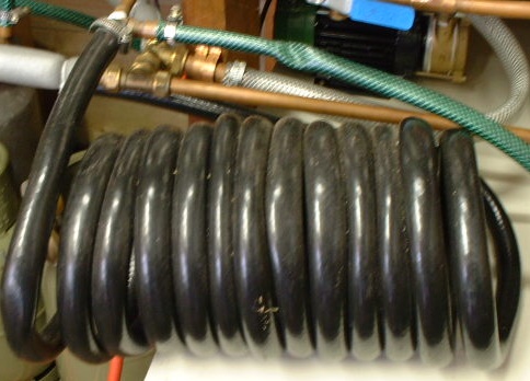
Back to the Top of the PageThe Counter flow chiller (CFC)
The Counter flow Chiller (CFC) is a great device that cools down a significant amount of beer (of approx. 100 °C) in a short time down to 20 °C. The CFC consists of a long copper pipe where the hot wort flows through. Placed over this copper pipe is a black hose. Inside this hose cooling water is flowing. The flow is opposite to the flow of the beer in the copper pipe. This ensures an amazing cooling efficiency. A CFC always has 4 connections: beer in, beer out, cooling water in, cooling water out. The picture only shows two connections (other two connections are outside the picture). The green hose on the picture is the 'cooling water out' connection. To the right you can see the 'beer in' connection. The 'beer out' connection (not shown on the picture) is a hose that I hang in the fermentation bin.
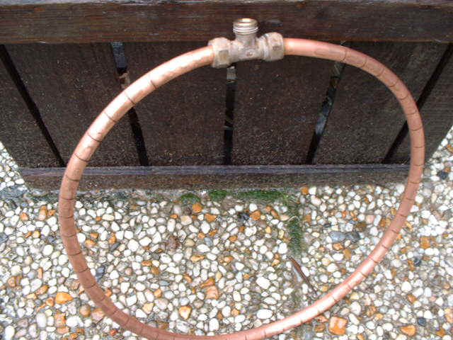
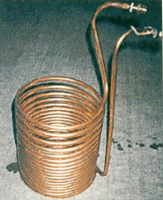
I used to work, like many home-brewers, with an immersion chiller (see picture). Cooling water if flowing through and the chiller itself is placed inside the wort. It took an hour of continuous stirring (very annoying) before the beer was cooled down sufficiently. And below 60 °C you might have a chance of getting an infection in your beer (this is impossible with the CFC, since it never comes into touch with air during cooling). My immersion chiller has evolved into the counter flow chiller: I used all the copper from the immersion chiller as the inside for my CFC. The biggest problem here was to span the black hose over the copper (needed a few bottles of olive oil to get the job done!).
 Back to the Top of the Page
The gas burners
There's a lot to tell about different ways of heating. I used to have a relatively small burner on propane/butane gas. The first modification was to convert this burner to natural gas. The disadvantage of this burner was the limited amount of power (8 kW, 27000 BTU/hour). If you use this burner in combination with an electric heating element, performance becomes acceptable. I used this solution for a couple of years on the HLT.
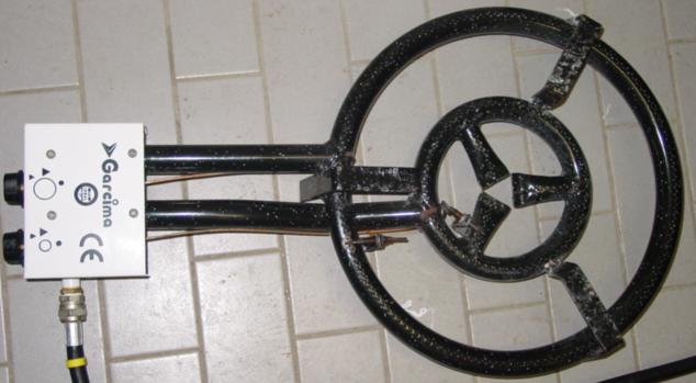
But I needed more power for the boil kettle. One of the things I came up with, was a so-called paella burner, made by Garcima. These burners have a power of 12.5 kW (42000 BTU/hour), which is barely enough to get 80 litres to a rolling boil. The main disadvantage of this burner is the price. It did cost me 200 euro at Brouwland! I don't like to spend so much money on a burner, but after a long thought, I bought it anyway. This burner also served me well for a couple of years.
But the story continues... one of my neighbours happens to be a plumber. He regularly supplies me with old central-heating boilers (if he installs a new one, he removes the old one). Basically, such a central-heating boiler is an excellent brewing device, with many interesting components on-board. There's a lot of variation between these boilers: the old ones are non modulating (the burner is either ON or OFF), the newer boilers are modulating (controlled between 0 and 100 %).
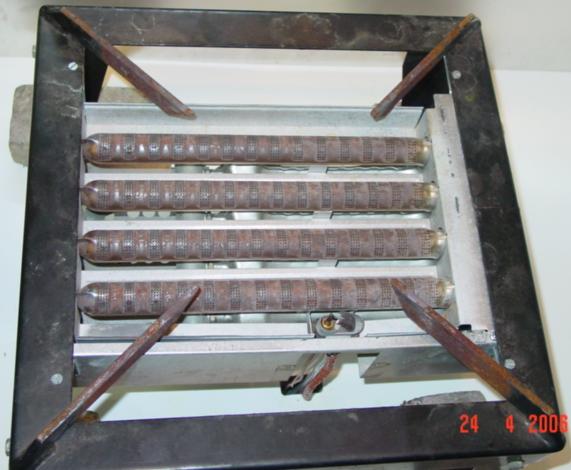
After dismantling several of these boilers, I found out that the most interesting boilers are the AGPO Ferroli 1324T boilers. These boilers contain a modulating gas valve, type V4600N from Honeywell (electric modulating regulator is the V7335A). This gas-valve is relatively easy to control (28 Vdc pulse-width-modulated signal). I have the brew program (with its built-in PID controller) control the gas burner under the HLT. It's a beautiful thing to see the brew program automatically adjusts the flames under the HLT. For the burner under the boil kettle I created some electronics, with which you can control the flames with a pot meter. I prefer to control this manually. But the gas burner itself (from the central-heating boiler) is the masterpiece. It is a brutal 24 kW (82000 BTU/hour)! And this is a lot of heat when it is fully open. It is more than sufficient for my brewing setup. Even when the burner is only at 50%, my brewery becomes tropical within a few minutes! Another very convenient gadget (came also with the boiler) is the electric spark ignition. Turn the gas on, press a button, and the pilot light is on! Just take care of proper grounding, otherwise the sparks disturb the electronics.
The latest additions are the electric heating elements. I can now heat with a gas-valve, with 1 or 2 heating-elements or with all of them. All controlled by the brewing program. The current install of electric heating is 4500 W and added to the gas-valve power, heating a completely filled HLT is done relatively quickly.
Back to the Top of the PageTemperature controlled Fermentation
A climate chamber is not really a part of the brewing-setup? In fact it is, but often it is not the first part that you want to build yourself. For years I have brewed without a climate chamber. But only if you have one in use, you realize how big the difference is. My beers were always a bit too sweet, yeasting often stopped a bit too early. Where a beer normally would have a final gravity of around SG 1010-1012, my beers ofted had 1016-1020 as final gravity, leading to a beer that was always a bit too sweet. After having built a climate chamber, this changed signifcantly. Yeast is susceptible for changes in temperature and by giving the yeast a very constant temperature, the yeasting process continues for a longer time. And this does a lot of good for your beers.
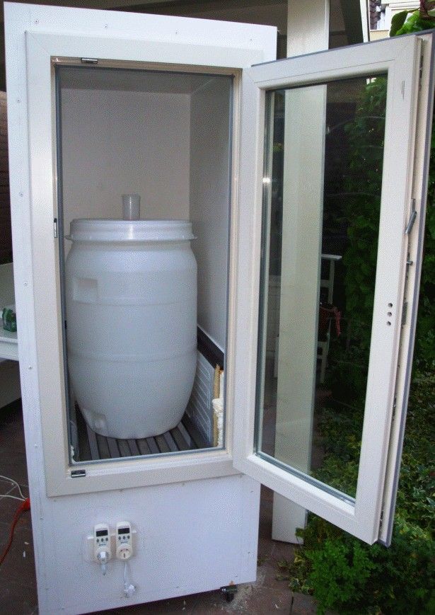
Building such a climate chamber starts with buying an old fridge, a toploader in my case. The small cooling tracks ran through the sides of the fridge, not the front. So I cut out the entire front of the fridge and made a wooden frame surrounding the entire fridge. I added a vinyl window frame to the front, (barely) large enough for a fermentation bin of 120 L. Good decent insulation has been added to the sides of the wooden frame an everything is properly finished with trespa plates. All wiring of the fridge has been completely stripped, including the existing thermostat. The only connection left was the connection for the motor of the compressor. Heating the interior is done with heating foils, which I bought at an online electronics store: Conrad (www.conrad.nl, order number is 189297-89). The power per foil is 65 W, size is 30 x 12 cm and they can be directly connected to 230 V AC. I added this heating foil to a stainless steel plate with a fan underneath. The entire construction is placed on the bottom of the fridge. In total I used two of these heating foils, which is sufficient for the internal volume of the climate chamber.
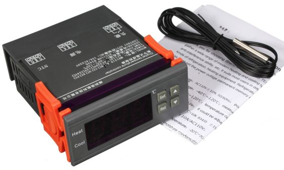
Controlling both the compressor of the fridge and the heating plates is done with a digital thermostat, which is readily available on ebay. Just search for STC-1000. This is a thermostat with a temperature sensor, that can both cool and heat. The temperature sensor is of course built inside the climate chamber, the thermostat itself has been mounted to the front of the climate chamber.
This climate chamber was used for approx. 15 years, more recently I decided to invest in conical fermenters. I bought a total of four Grainfather conical fermenters with a glycol-chiller.
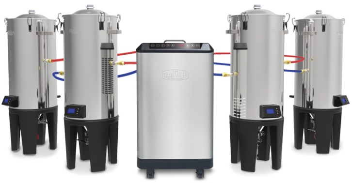
This is an ideal combination if you brew small batches of only 20-25 liters. The glycol chiller is capable of maintaining cooling temperature of four fermenters and is able to cold-crash one fermenter. These fermenters also have a built-in heating-element and the controller mounted to the fermenters takes care of maintaining the setpoint temperature.
For brewing larger batches (80 liters) I bought a Brewtools F100 Unitank.
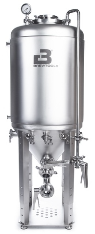
This Unitank can no longer be considered as a 'hobby' fermenter, it is a professional conical fermenter. I connected another Grainfather Glycol chiller to it, to control cooling. I used a modified STC-1000 for this purpose. The F100 Unitank also has a 500 W heating-element and the STC-1000 controls both heating and cooling.
Back to the Top of the Page